P-NET in Architecture
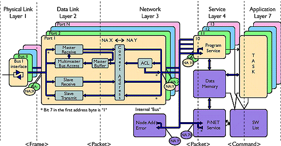
P-NET is specified and implemented according to the Open Systems Interconnection Reference Model, on layers 1, 2, 3, 4, and 7, as shown in the diagram in fig. 11.
Normally, a Fieldbus is only implemented on layers 1, 2 and 7, but since P-NET features the multi-net structure, the protocol also implements layers 3 and 4.
Layer 1 is concerned with transmitting raw bits over the bus. It specifies the cable, how a ‘1’ and a ‘0’ is represented on the bus, what the voltage level is, etc.
Layer 2 takes care of the multi-master token, packs the data to be sent into a frame, including source and destination addresses, and performs error detection.
Layer 3 is the P-NET ‘post office’, which receives and sends the frames according to the destination address. A message may be required to be sent out of another P-NET port, or into the P-NET service, or back to the requesting application, or return a message indicating an unknown address. It also performs the address conversion necessary to ensure a response finds its way back.
Layer 4 handles two different tasks. The first provides the P-NET service, which reads or writes data to internal memory via the SOFTWIRE list, or reroutes a request, if the SOFTWIRE list indicates that the variable is located in another node.The second task holds details about the number ofrequests which have been sent out but are waiting for a reply. When the reply arrives, it is sent back to the calling application task.
Layer 7 is used by application programs to access variables in other nodes. This is done by sending a command block containing references to the SOFTWIRE list, which is where detailed information such as node address, internal address etc.is specified.
The SOFTWIRE list is also used for internal variables.
